A full-chain daylight EL inspection of a 100 MW PV plant produces tens of thousands of individual EL frames. Without stitching, each frame is an isolated fragment with little operational value. With AI-based panorama stitching, those frames become a single continuous map that maintenance teams can navigate, compare, and act upon.
The Data Deluge Problem
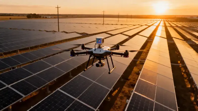
Modern daylight EL drones capture at 1–3 frames per second during a pass over a PV string. A typical 300-meter string of 72-cell modules requires 12–16 frames to cover the full length at the resolution needed for defect detection. For a 100 MW plant with roughly 1500 strings, that is 20,000–25,000 frames per inspection campaign.
Viewing those frames individually is operationally useless. Technicians cannot correlate defects to specific modules, cannot compare year-over-year changes, and cannot hand off findings to repair crews without spending days manually cross-referencing positions.
What Stitching Solves
Panorama stitching converts the frame sequence into a single wide image of the entire string. Once stitched, the image becomes:
- Navigable: Pan/zoom in any viewer, jump to specific module numbers
- Comparable: Overlay with last year's inspection to spot new defects
- Shareable: A single file per string instead of dozens
- Quantifiable: Defect density, distribution, and clustering can be measured at string level
The AI Stitching Pipeline
A production-grade stitching pipeline runs through:
1. Geometric calibration
Each drone camera has lens distortion and mounting offset. Calibration using a known reference removes these artifacts before stitching.
2. Feature detection
AI models identify reference features — module frames, junction boxes, string boundaries — that serve as alignment anchors. Classical feature descriptors (SIFT, SURF) fail on uniform module surfaces; learned feature networks trained on PV imagery perform significantly better.
3. Overlap matching
Adjacent frames typically share 20–40% overlap. The matcher finds corresponding features across frame pairs and computes the geometric transformation (homography) that aligns them.
4. Seam blending
Where frames overlap, pixel values must be blended to hide seams. Simple averaging creates double-exposure artifacts; modern pipelines use Laplacian pyramid blending or learned blending networks for clean transitions.
5. Radiometric normalization
EL intensity varies frame-to-frame due to current fluctuations, ambient light changes, and sensor gain variations. Normalization ensures defect contrast is consistent across the panorama.
6. Coordinate registration
The final panorama is registered to the plant GIS coordinate system, enabling automatic module-ID tagging and cross-referencing with inverter data.
Typical Pipeline Performance
On a modern workstation with GPU acceleration, the full stitching pipeline processes:
- Single-string panorama (14 frames): 8–15 seconds
- Full 100 MW plant: 4–6 hours unattended
- Incremental updates: 30 seconds per changed string
The Vision Potential daylight EL drone platform (SC-DEL-Drone) outputs frames tagged with GPS, altitude, and camera orientation metadata, which reduces the stitching workload by eliminating the search for global alignment.
Output Formats for O&M Use
Stitched panoramas are typically produced in three formats:
- Full resolution TIFF for archive and defect measurement (10–50 MB/string)
- Progressive JPEG for web viewer use (500 KB–2 MB/string)
- Tiled deep-zoom (DZI/IIIF) for seamless pan/zoom in O&M dashboards
Modern O&M software integrates tiled panoramas with defect heatmaps, allowing technicians to click any suspected defect and see the original high-resolution EL frame, the visible-light aerial reference, and historical comparisons.
Before-and-After Field Practice
A 50 MW plant in southern Europe recently transitioned from per-frame review to stitched panorama review. The operational metrics changed sharply:
| Metric | Per-frame | Stitched panorama |
|---|---|---|
| Review time per string | 8–12 min | 1–2 min |
| Defects missed on first pass | 6% | <1% |
| Time to generate repair work order | 2–3 days | Same day |
| Year-over-year comparison feasible | No | Yes |
Integration With Repair Workflows
The stitched panorama becomes the handoff artifact from inspection to repair. Technicians receive:
- A link to the panorama viewer centered on the affected area
- Module-level coordinates for the defect
- Historical overlay showing whether the defect is new or existing
- Severity classification suggesting repair priority
Repair crews arriving on-site have every detail they need to locate and address the issue without returning to base for clarifications.
Common Pitfalls
- Incomplete overlap: Flights that leave 10% or less overlap produce stitching failures at seams. Mission planning should target 30% minimum.
- Uneven illumination: Late-afternoon glancing sun creates harsh shadows that fool alignment. Inspect during solar noon ±2 hours.
- Cell-type mixing: Strings containing both PERC and TOPCon modules produce intensity discontinuities that stitching must normalize. Flag cell type per string in mission metadata.
- Drone motion blur: Frames captured during turns or altitude changes blur unusably. Limit capture to stable-flight segments only.
The Strategic Layer
Panorama stitching enables the transition from reactive inspection to proactive asset management. Plants that maintain an annual panorama archive build a longitudinal dataset showing defect evolution. Combined with production monitoring data, that dataset feeds forecasting models for degradation rate, warranty claim timing, and repower economics.
For larger portfolios — 1 GW and above — stitched panoramas are the minimum viable data product. Without them, asset management decisions revert to averaged performance data that hides critical string-level patterns.